| << Chapter < Page | Chapter >> Page > |

When running
impsys.m , there are two suggested
nonzero choices for the phase offset parameter
po .
With
po=0.9 ,
, and
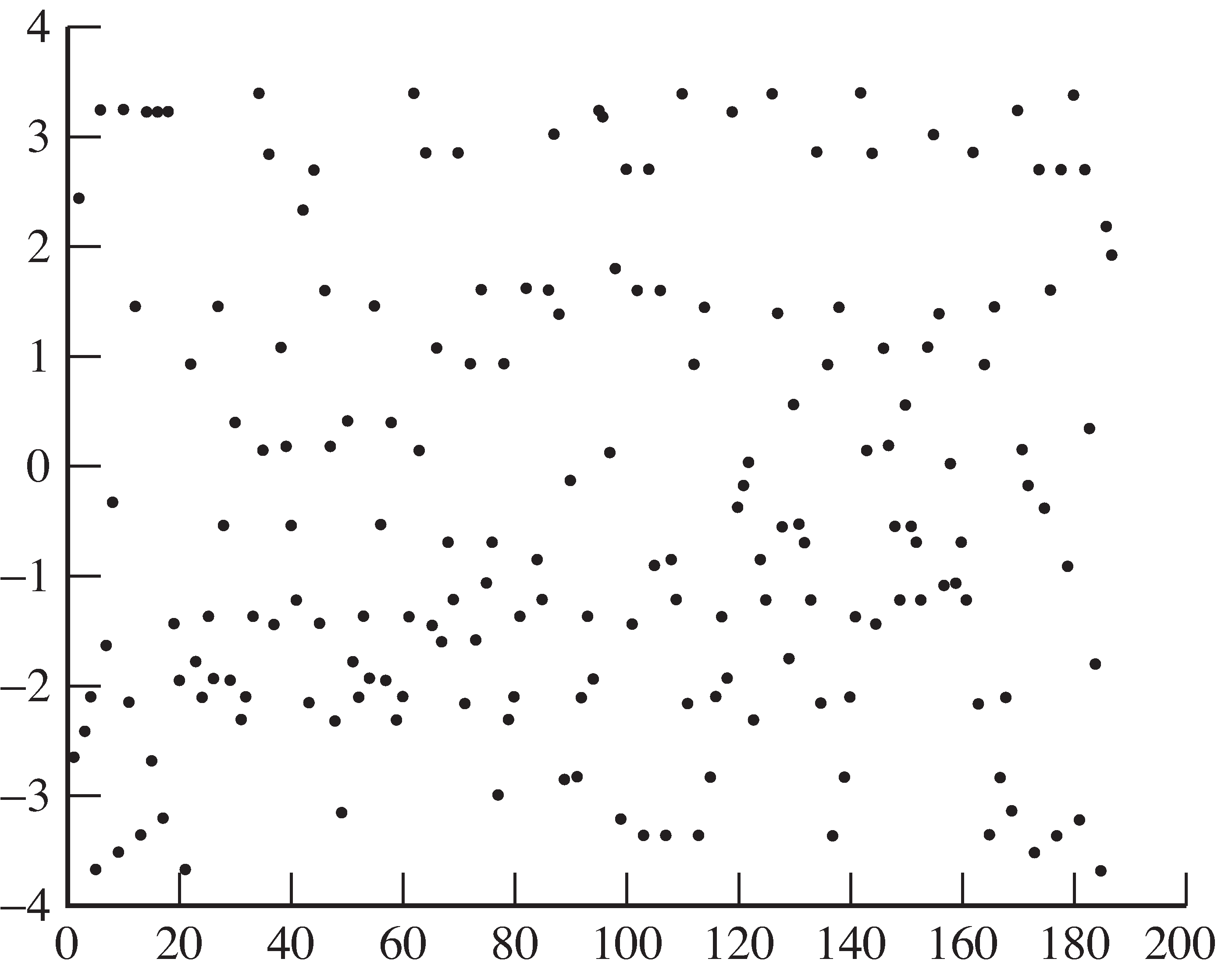
. This is shown in the plot of the
soft decision errors in
[link] .
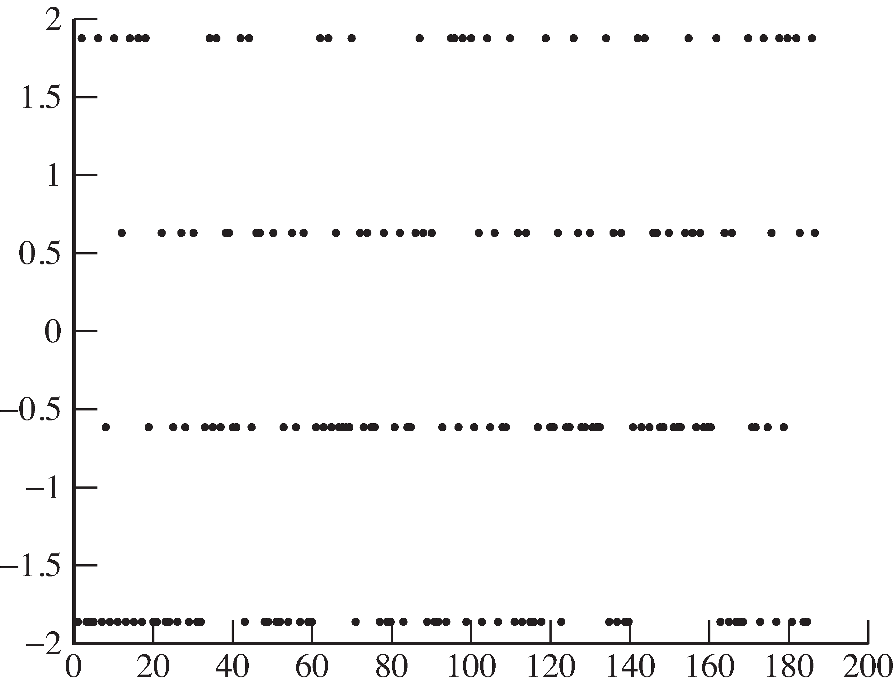
For the milder carrier phase offset (
po=0.7 ),
the soft decisions result in no symbol errors,because the quantizer will still decode values at
as
.

As long as the constellation diagram retains distinct horizontal stripes, all is not lost.In [link] , even though the maximum magnitude is less than two, there are stillfour distinct stripes. If the quantizer could be scaled properly, the symbols could be decoded successfully.Such a scaling might be accomplished, for instance, by another AGC, but such scaling would not improve thesignal-to-noise ratio. A better approach is to identify the `unknown' phase offset, as discussed in Chapter 10.
Using
impsys.m as a basis, implement an AGC-style
adaptive element to compensate for a phase offset.Verify that your method works for a phase offset of
and for a phase offset of
.
Show that the method fails when the phase offsetis
.
The receiver in
[link] has
a carrier frequency offset whenthe frequency of the carrier at the transmitter
differs from the assumed frequency of the carrier at thereceiver. As was shown in
[link] in
[link] ,
this impairment is like a modulation bya sinusoid with frequency equal to the offset.
This modulating effectis catastrophic when the low frequency modulator
approaches a zero crossing, since then the gain of the signalapproaches zero.
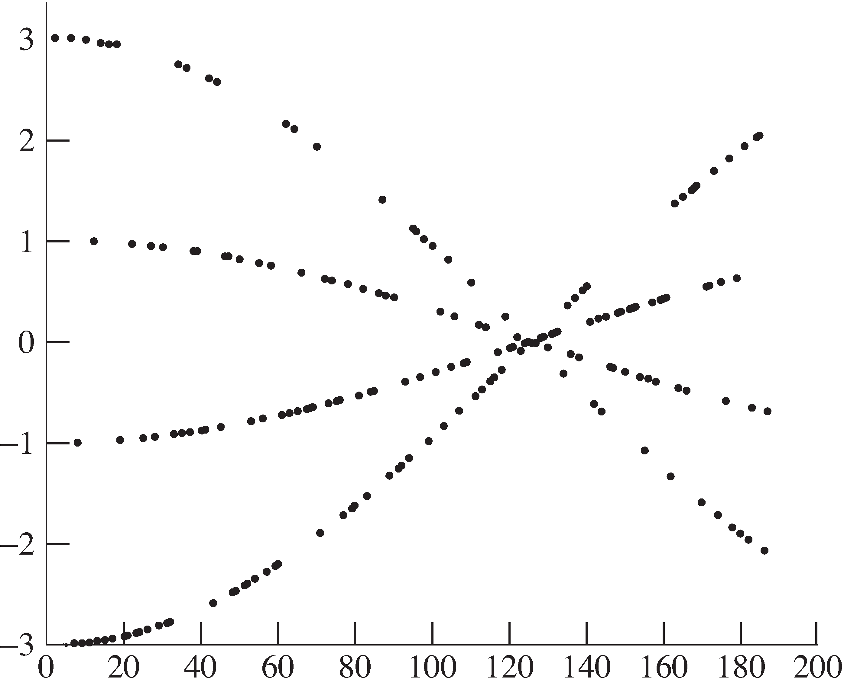
This effect is apparent for a 0.01% frequency offsetin
impsys.m in the plot of the soft decisions
(via
plot([1:length(z)],z,'.') )
in
[link] .
This experiment suggests that receiver mixer frequencymust be adjusted to track that of the transmitter.

As shown in
[link] ,
there is a sequence of “best times” at which to downsample.When the starting point is correct and no intersymbol
interference (ISI) is present,as in the ideal system,
the sample times occur at the top of the pulses.When the starting point is incorrect,
all the sample times are shiftedaway from the top of the pulses.
This was set in the ideal simulation using theparameter
, with its default value of 125.
The timing offset parameter
toper in
impsys.m is used to offset the received signal. Essentially,
this means that the best value of
has changed, though
the receiver does not know it.
This is easiest to see by drawing the eye diagram.
[link] shows an overlay of 4-symbol
wide segments of the received signal (using the
reshape command).
The receiver still thinks the best times to sampleare at
, but this is clearly no longer true.
In fact, whenever the sample time begins between100 and 140 (and lies in this or any other shaded region),
there will be errors when quantizing.For example, all samples taken at 125
lie between
, and hence no symbols
will ever be decoded at their
value.
In fact, some even have the wrong sign!This is a far worse situation than in the carrier
phase impairment because no simple amplitude scalingwill help. Rather, a solution must correct the problem;
it must slide the times so that they fall in theunshaded regions. Because these unshaded regions
are wide open, this is often called the
open eye region. The goal of an adaptive element designed to
fix the timing offset problem is to
open the eye as wide as possible.

Notification Switch
Would you like to follow the 'Software receiver design' conversation and receive update notifications?