| << Chapter < Page | Chapter >> Page > |
As we have seen in previous sections, an electric circuit is made up of a number of different components such as batteries, resistors andlight bulbs. There are devices to measure the properties of these components. These devices are called meters.
For example, one may be interested in measuring the amount of current flowing through a circuit using an ammeter or measuring the voltage provided by a battery using a voltmeter . In this section we will discuss the practical usage of voltmeters, ammeters, and ohmmeters .
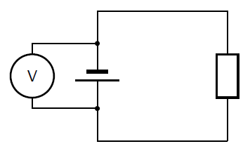
A voltmeter is an instrument for measuring the voltage between two points in an electric circuit. In analogy with a water circuit, avoltmeter is like a meter designed to measure pressure difference. Since one is interested in measuring the voltage between twopoints in a circuit, a voltmeter must be connected in parallel with the portion of the circuit on which the measurement is made.

[link] shows a voltmeter connected in parallel with a battery. One lead of the voltmeter is connectedto one end of the battery and the other lead is connected to the opposite end. The voltmeter may also be used to measure thevoltage across a resistor or any other component of a circuit that has a voltage drop.
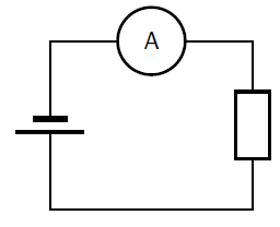
An ammeter is an instrument used to measure the flow of electric current in a circuit. Since one is interested in measuring thecurrent flowing through a circuit component, the ammeter must be connected in series with the measured circuit component ( [link] ).

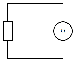
An ohmmeter is an instrument for measuring electrical resistance. The basic ohmmeter can function much like an ammeter. The ohmmeterworks by suppling a constant voltage to the resistor and measuring the current flowing through it. The measured current is thenconverted into a corresponding resistance reading through Ohm's Law. Ohmmeters only function correctly when measuring resistance over a componentthat is not being powered by a voltage or current source. In other words, you cannot measure the resistance of a component that isalready connected to a live circuit. This is because the ohmmeter's accurate indication depends only on its own source ofvoltage. The presence of any other voltage across the measured circuit component interferes with the ohmmeter'soperation. [link] shows an ohmmeter connected with a resistor.

A good quality meter used correctly will not significantly change the values it is used to measure. This means that an ammeter hasvery low resistance to not slow down the flow of charge. A voltmeter has a very high resistance so that it does not add another parallel pathway to the circuit for the charge to flow along.
If possible, connect meters in circuits to get used to the use of meters tomeasure electrical quantities. If the meters have more than one scale, always connect to the largest scale first so that the meter will not be damaged by having to measure values that exceed itslimits.
The table below summarises the use of each measuring instrument that we discussed and the way it should be connected to a circuitcomponent.
| Instrument | Measured Quantity | Proper Connection |
| Voltmeter | Voltage | In Parallel |
| Ammeter | Current | In Series |
| Ohmmeter | Resistance | Only with Resistor |
The following presentation summarizes the concepts covered in this chapter.
| Quantity | Symbol | Unit of meaurement | Symbol of unit |
| e.g. Distance | e.g. d | e.g. kilometer | e.g. km |
| Resistance | |||
| Current | |||
| Potential difference |

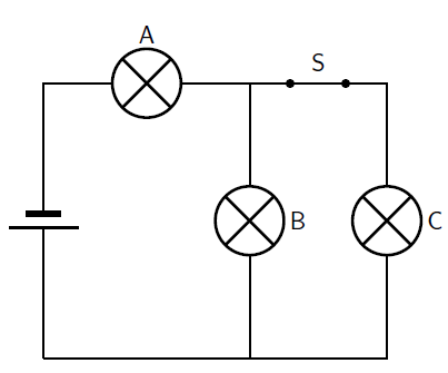
| Current in A | Current in B | |
| (a) | decreases | increases |
| (b) | decreases | decreases |
| (c) | increases | increases |
| (d) | increases | decreases |

Notification Switch
Would you like to follow the 'Siyavula textbooks: grade 10 physical science' conversation and receive update notifications?