| << Chapter < Page | Chapter >> Page > |
An instruction has a number of stages. The various stages can be worked on simultanously through various blocks of production. This is a pipeline. This process is also referred as instruction pipeling. Figure 8.1 shown the pipeline of two independent stages: fetch instruction and execusion instruction. The first stage fetches an instruction and buffers it. While the second stage is executing the instruction, the first stage takes advantage of any unused memory cycles to fetch and buffer the next instruction. This process will speed up instruction execution

Figure 8.1. Two stages Instruction Pipeline
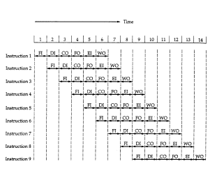
The decomposition of the instruction processing by 6 stages is the following.
- Fetch Instruction (FI): Read the next expected introduction into a buffer
- Decode Instruction (DI): Determine the opcode and the operand specifiers
- Calculate Operands (CO): Calculate the effective address of each source operand. This may involve displacement, register indirect, indirect or other forms of address calculations.
- Fetch Operands (FO): Fetch each operand from memory. Operands in register need not be fetched.
- Execute Instruction (EI): Perform the indicated operation and store the result, if any, in the specified destination operand location.
- Write Operand (WO): Store result in memory.
Using the assumption of the equal duration for various stages, the figure 8.2 shown that a six stage pipeline can reduce the execution time for 9 instructions from 54 time units to 14 time units.

Figure 8.2. Timing diagram for instruction pipeline operation.
Also the diagram assumes that all of the stages can be performed in parallel, in particular, it is assumed that there are no memory conflicts. The processor make use of instruction pipelining to speed up executions, pipeling invokes breaking up the instruction cycle into a number of separate stages in a sequence. However the occurrence of branches and independencies between instruction complates the design and use of pipeline.
With the pipeling approach, as a form of parallelism, a “good” design goal of any system is to have all of its components performing useful work all of the time, we can obtain a high efficiency. The instruction cycle state diagram clearly shows the sequence of operations that take place in order to execute a single instruction.
This strategy can give the following:
- Perform all tasks concurrently, but on different sequential instructions
– The result is temporal parallelism.
– Result is the instruction pipeline.
In this subsection, we can show some measures of pipeline performance based on the book “Computer Organization and Architecture: Designing for Performance”, 6th Edition by William Stalling.
The cycle time of an instruction pipeline can be determined as:
with 1 i k
where:
= Maximun stage delay through stage
k = number of stages in instruction pipeline
d = time delay of a latch.

Notification Switch
Would you like to follow the 'Computer architecture' conversation and receive update notifications?